Background
I have a mechanical keyboard addiction…
I have been a keyboard nerd for as long as I remember, the touch, the
sound. I have always looked for the best keyboard.
As a kid my father got me a nice keyboard, I don’t even recall the
brand; but that thing was amazing and I absolutely loved it’s feeling.
I loved it so much in fact that I would clean it often with window
cleaning product, but I went a little overboard with the cleaning and
it shorted; I was so sad, it’s been more than 15 years and I still
remember to this day how I felt when that happened.
Fast forward to now, and I now have a small collection of 5-ish
keyboards.
In the past years or so I’ve focused on ergonomic keyboards, because
they look cool and unusual but also because it’s said that they help
with Carpal Tunnel
Syndrome
prevention, which is every computer nerd’s fear.
I got myself a Kinesis Advantage 2, a great (and very expensive) keyboard.
But as is often said, the keyboard must be one of the only things in
computing that hasn’t changed much since its inception; you could
pretty much use a keyboard from the 70’s on your 2020 macbook. So it’s
not that big of an investment when you think about it like that.
After a year of using it I got tired of those crappy Cherry MX brown
switches that ship with the Kinesis, I’m a clicky switch guy.
So I set out to find the switch that best suits my noisy requirements
and decided to change the switches on the Kinesis, a simple desolder
job right? HA!
(Clicky) Switch Selection
I got a switch tester from
KBDFans
with a 3x4 matrix of clicky switches from various brands.
Cherry switches’ quality has been known to be declining, and success
really depends on how lucky you are with the batch you receive.
On the other hand Chinese manufacturers like Kailh and Gateron have
been gaining quite the reputation, and quality is supposedly more
consistent.
I settled on Kailh Box White switches which had to me the perfect
balance between sound & weight. I’ve seen a lot of people praise the
Kailh Speed Bronze switches, but the actuation point (at which point
of the key’s travel is the key actually registered as pressed) felt too high for
me and the weight was too light.
On thing that’s unique (to my knowledge, and compared to cherry
equivalents) to Kailh switches, is that they use a “click bar”.
That means that the key actuation and the “click” noise mechanism are
actually seperate, and the other difference is that you have a click
up and down.
But the click they provide is quite unique.
u/Curioussilly has a great review of them over at reddit.
To quote him:
> The BOX whites are a light “clicky linear”, with a ~40g actuation force and ~50g bottom out force, lighter than the common Cherry MX Red/Blue/Brown switches which bottom out at around ~60g. Although often called a “clicky linear”, these actually have sort of a tactile bump on the way down (and up) thanks to that click bar. The tactile bump is really different from that of any clicky or tactile switch I’ve tried, and I’ll try to elaborate on that below.
Epic fail :picard:
I have found to other people out there which recorded their experience
with changing the switches on their Kinesis.
This guy, desolders the existing keys and puts his own on the
original PCB. He also notes:
I wish I’d known this before I started … As of 2015-04, Kinesis is willing to sell you all the boards (key well and thumbs) and the plastic retainers for them for about $30 US for the full set (email “techsupport@kinesis.com”).
Unfortunately as of 2020-01, Kinesis is not willing to sell
individual parts anymore. I can’t think of a reason why, but that’s
how it is.
Hello,
Thank you for your email. We sell the KIT-ADVANTAGE2 for $100 plus shipping. UPS to France quoted at $125 but that would be discounted to $57. This does not include any customs fees likely to be charged before delivery. The total due to Kinesis would be $157 USD.
If you would like to proceed please provide your phone number as well as the serial number for your keyboard.
Regards,
- Kinesis Corporation
www.Kinesis.com
That’s waaaay too much, especially since I only needed a few parts,
not all of them.. So fuck that; also I was expecting that a $350
keyboard from a small company would be more servicable than thath.
Then there’s that guy, who
gets rid of the PCBs and directly handwires all the keys.
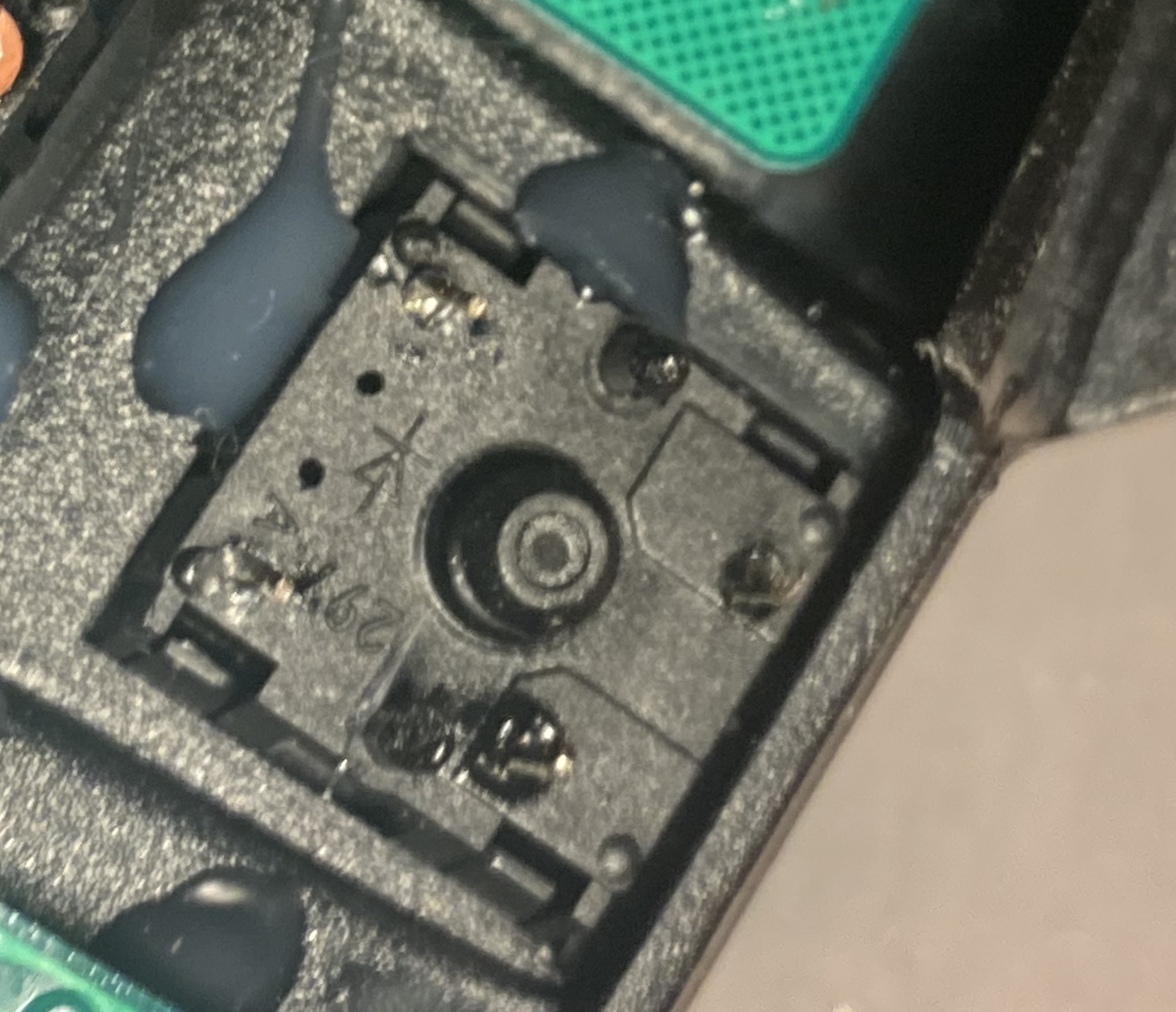
I initially set out to risk it and replace the switch on the PCB (like
Guy #1), but I failed miserably after the 3rd switch I was desoldering
and completely ripped one of the pads..
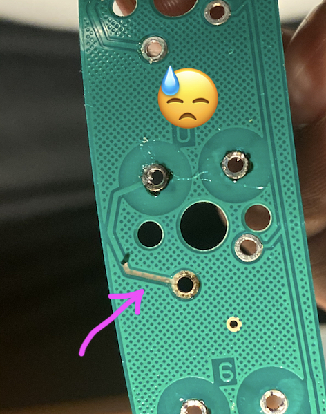
I don’t know how to fix that, or even if it’s fixable, so that was pretty much
game over…
Handwiring the beast
Inspired by Guy #2 I decided to
give handwiring a go, plus being a fervent follower of r/mk the Handwiring Way
always had an appeal to me. This is the way.
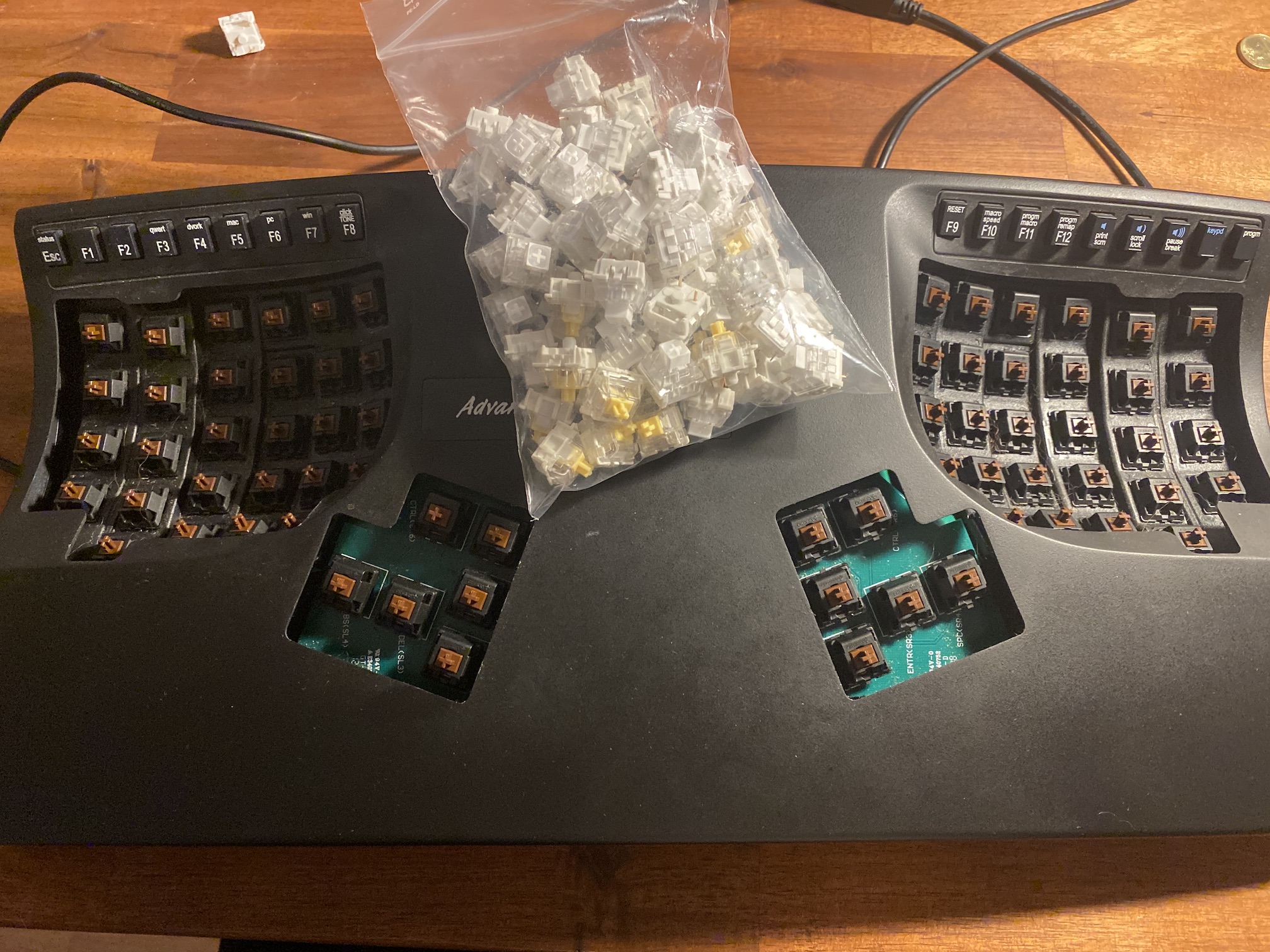
Step 1: Replacing the existing switches
My Advantage shipped with Cherry MX Brown switches, which don’t hold
much respect among the community, to be honest I feel that Cherry as a
whole doesn’t hold much respect, but that’s another topic.
As stated earlier I fucked up the PCB, so I didn’t take
much care with the rest of it, ripping it away as fast as I could.
Use a desolder pump to remove all
the solder holding the switches on the PCB.
Start from the top and remove it from each switches as you go.
Once the PCB is out of the way, you’ll have access to the switch
itself.
They are friction fitted on the keywell and hot glued for extra grip.
The hot glue is easy to remove, I rubbed acetone on the glue using a
q-tip, and a a pair of pliers to pull the glue away.
Once the glue is off, just push from beneath and the switch will pop
out.
Don’t over do it with the acetone as the keywell’s plastic could be
damaged, cheap plastic hates acetone; try to apply the acetone only on the glue.
Once all of the original keys have been removed, put yours in place.
For the switches on the keywell, PCB mounted or Plate mounted keys
will do, but plate is better (and PCB for the thumbs).
Step 1.a: The thumb clusters
I reused the original thumb clusters as the plate for my new switches,
it was the easier way.
I didn’t want to bother understanding how the thumb cluster’s PCB was
wired, so I handwired it too.
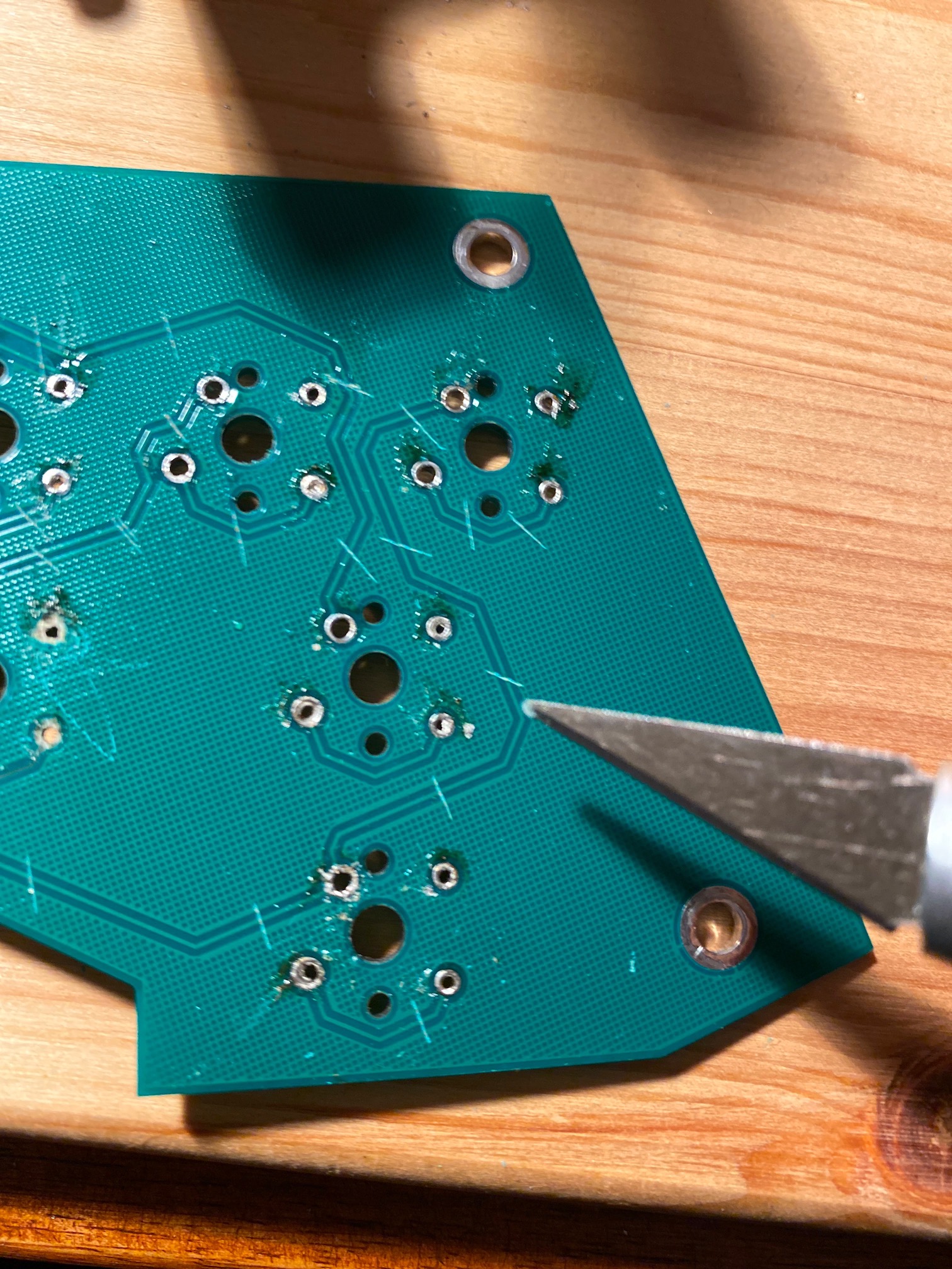
To achive this, I cut out all the traces on the existing PCB with an
exacto knife, and just used the PCB as a plate to mount the switches.
You will want PCB mounted switches for those; placing Plate mounted
switches perfectly on a PCB is a bit hard (and you’ll notice you
fucked up only when you place the key caps on the switches and they touch each
other).
Step 2: Diodes
I’m no expert, but basically all keyboards use a matrix to identify
which key is being pressed, identified by their row/column position.
To force the current to flow one way, a diode is place after each
key.
To put it simply, the controller will poll (ie. send current) to a column,
when a switch is pressed, that row will close the circuit back to the
controller; which will then know which key was pressed, it knows to
which column it sent the current and it knows on which row the circuit
was closed… I hope that makes sense.
More details on the inner workings of keyboards and why you need
diodes can be found on QMK’s excellent guide.
For wholesale, Cherry offers switches with integrated diodes, this
won’t be accessible to you (or me).
So you need to buy & solder diodes yourself, I bought 1N4148 diodes from conrad.fr,
the 1N4148 are the ones you see recommended in every guide, it’s dirt
cheap and perfect for the job.
There are some variants in specs (mA rating, voltage), I got the 75V 150mA variant
and it works.
Diodes have an orientation, the current flows in from
the “orange” part and exits through the black end, be mindful of that,
if one of them is not in the correct orientation, that whole column of
keys (starting with the misplaced diode) will not work.
To make your life easier, close to the diode’s body, on the orange
side of the diode, bend the wire using a pair of needle node pliers
and wrap the wire along one half of the plier; in order to make a
loop.
Do that for all the diodes you will need.
The tighter the loop the better, but not too tight or you won’t be
able to slide it on the switch’s contact.
The orientation of the switch doesn’t matter, it’s just a switch, but
for your sanity’s sake, place them all in the same orientation.
Place the loop along bottom-most (in my case) switch contact, using
two pairs of pliers, tighten the loop around the contact by pulling on each side
gently.
Now using your soldering iron, heat up both the contact and the
wire (important to have a nice solder joint); and let the solder
flow inside the loop.
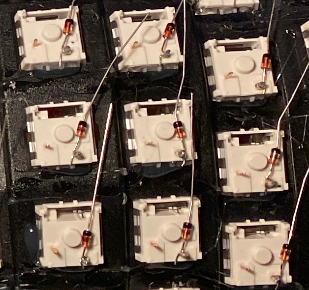
Cut off the excess wire from the diode; leave the other end of the
wire as is for now (like on the following picture); and you’re set.
Step 3: Matrix diagram
I initially made the mistake of thinking I could just wire that shit
without thinking about it.. Nope. You need to think this through, or
listen to me :)
Using the excellent kb firmware builder to
visually create the keyboard matrix and link to the controller’s pins
was incredibly time saving. (You can find the base layout preset of
the kinesis here and
import that into kb firmware builder).
Note:
I’ve always found the Function keys row on the Advantage to be poorly
designed (and also I was a real pain to desolder, really) so I’m not
using them for now.
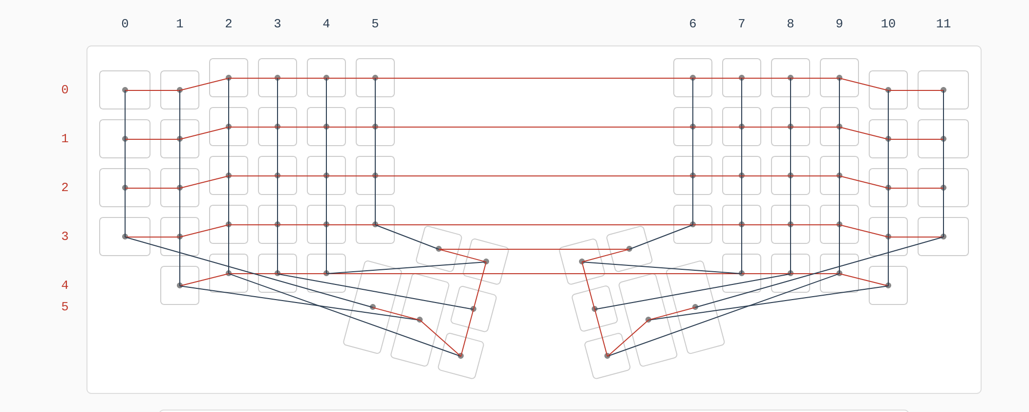
I went with a 6 rows and 12 columns matrix, the thumb clusters look
quite messy on the matrix screenshot, that’s because all the thumb
keys are actually represented as one row in my wiring.
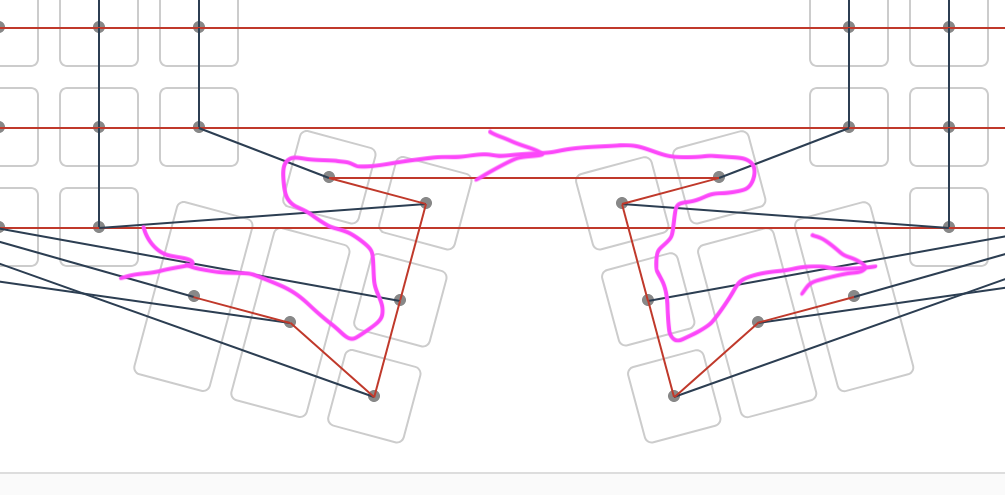
The only important thing to consider when wiring a keyboard is that
each key must be uniquely identified by it’s row/column index.
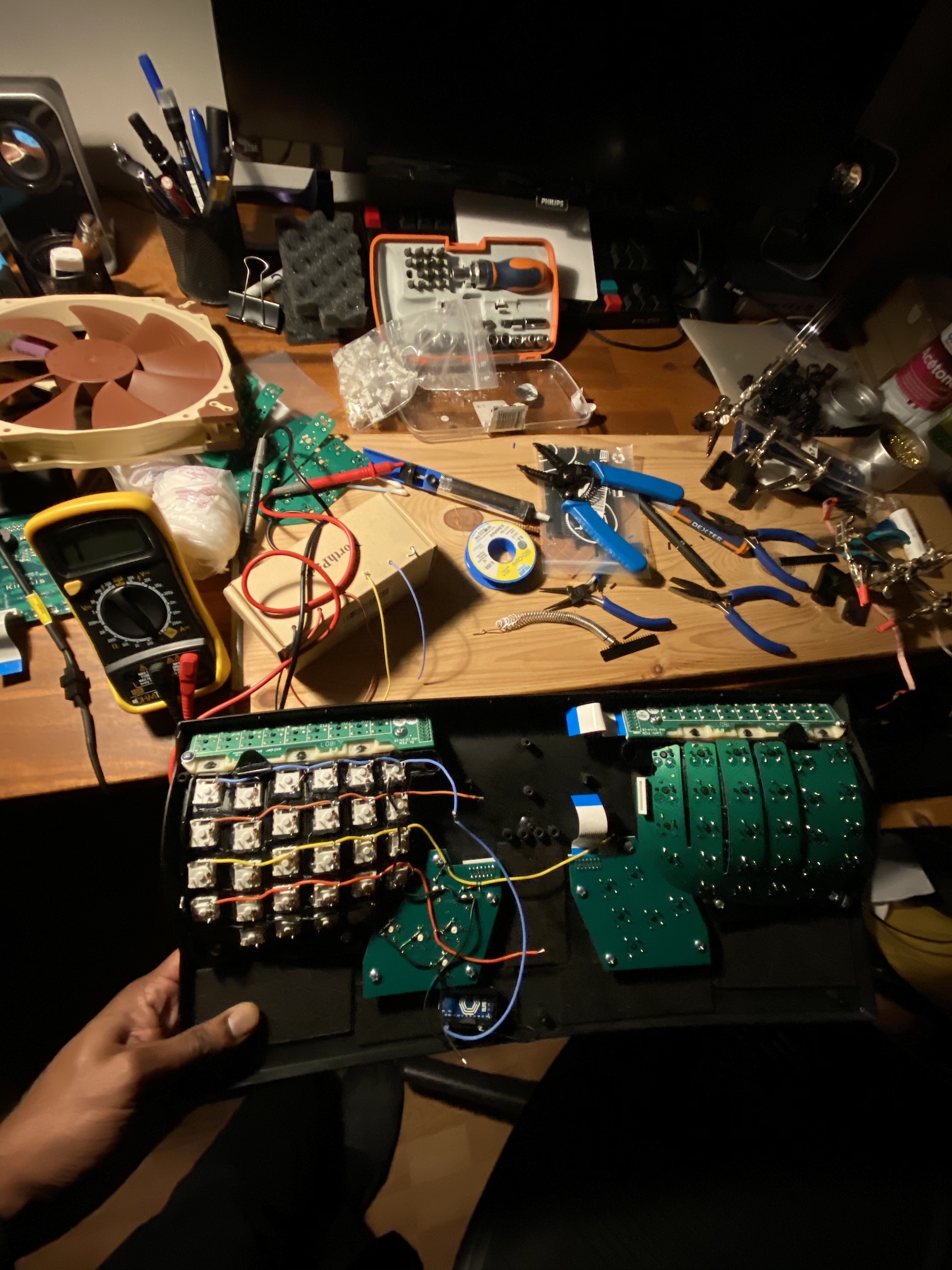
Step 4: Wiring it
 The thumb cluster is wired wrong on that picture btw!
I started with the rows, religiously following the diagram, then did
the columns.
I decided to wire each side seperately and join them later, I would
advise against that and just wire the whole row at once.
Take a length of wire that spans across both sides and be generous
with it, I got stingy and wire management ended up being a mess; you
can always trim down what you don’t need later.
Using a wire stripper
expose a bit of wire at regular intervals and wrap the remaining wire
from the diode around the stripped part, then cutting off the excess
diode wire, like on the following picture.
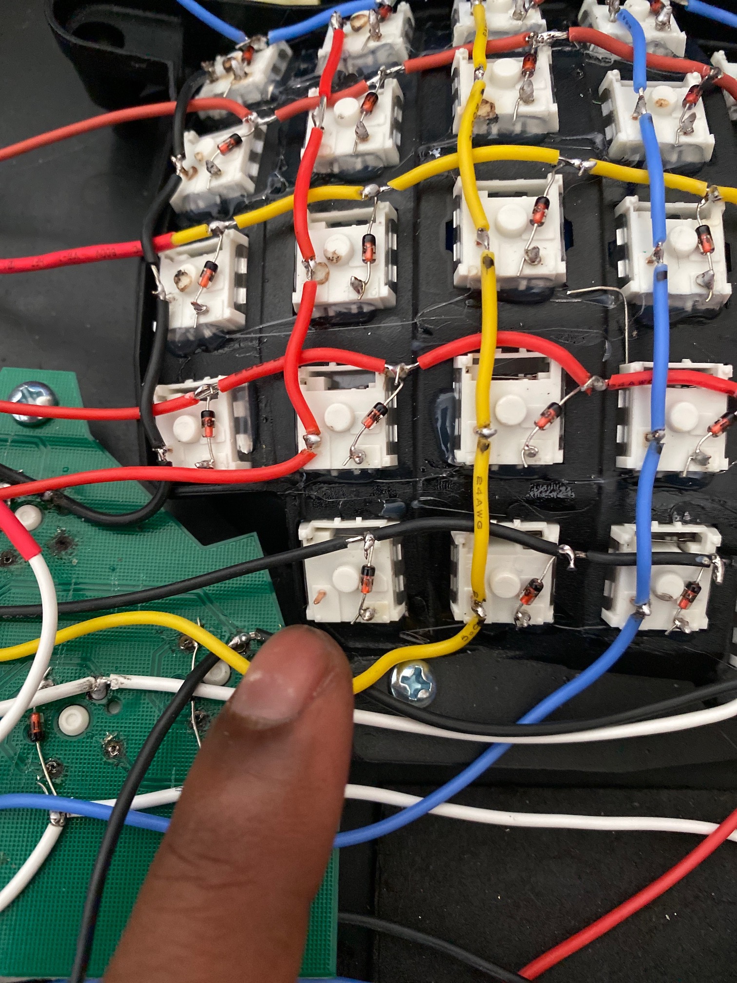 Note: I forgot to wire this key….
I was stripping the wires as I was going, switch by switch; I found it quite hard to
predict exactly where I should be stripping.
Once you’re done with the rows, do the columns, again use enough wire
so that you can do some cable management.
In the end all the wire will end up being connected to the controller,
which I placed at the bottom in between the two sides.
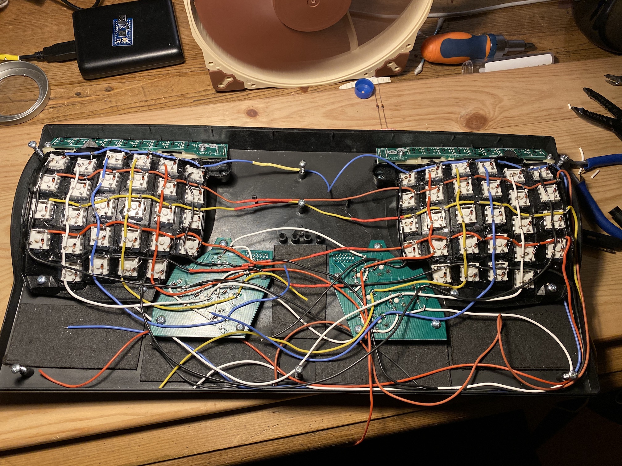
I did a very poor job at this, don’t be this guy, don’t be me :)
It should look something like this when you’re done; I can’t stress
this enough, I did not use long enough wires most of the time and it
resulted in a cable mess.
Using enough wire will allow you to bundle related wires toghether and
make everything much cleaner than this mess.
Once you have every rows, and columns wired according to your diagram
you need to connect them to the controller.
I used an Elite Proton C which is a Pro Micro
with USB-C connection. It runs the Atmega32u4 chip.
When designing the matrix on kbfirmwarebuilder you also chose which
pins of the controller go to which column and rows.
Following that I soldered the wires directly on the pro micro board,
I’m not proud of the job, it’s awfully messy.
But to be honest, once everything was wired and it actually worked… I
hot glued a wire inside the case to hold the controller in place and
never looked back.

Firmware
The QMK version used by Kb Firmware Builder is somewhat
outdated. I used it to generate the keyboard files and pasted that
into a recent version of QMK (the version from the website did not
have proper macro support for instance).
Just copy the files from the keyboards folder into a fresh QMK
clone or use my fork.
Since I didn’t wire the Function row from the original keyboard, I’m
using a layer shift on the numbers row to access F1, F2, etc. keys.
Here is the keymap:
const uint16_t PROGMEM keymaps[][MATRIX_ROWS][MATRIX_COLS] = {

	[BASE] = KEYMAP(
		KC_EQL   , KC_1   , KC_2    , KC_3     , KC_4    , KC_5           , KC_6        , KC_7        , KC_8     , KC_9   , KC_0      , KC_MINS   ,
		KC_TAB   , KC_Q   , KC_W    , KC_F     , KC_P    , KC_G           , KC_J        , KC_L        , KC_U     , KC_Y   , KC_SCOLON , KC_BSLASH ,
		KC_LCTRL , KC_A   , KC_R    , KC_S     , KC_T    , KC_D           , KC_H        , KC_N        , KC_E     , KC_I   , KC_O      , KC_QUOTE  ,
		KC_LSFT  , KC_Z   , KC_X    , KC_C     , KC_V    , KC_B           , KC_K        , KC_M        , KC_COMMA , KC_DOT , KC_SLASH  , KC_RSFT   ,
		                KC_GRV   , GUISPACE , KC_LEFT , KC_RIGHT           , KC_DOWN   , KC_UP , KC_LBRACKET , KC_RBRACKET ,


	KC_BSPC  , KC_ESCAPE , KC_LALT  , MO(ALT)  , KC_LCTRL , KC_LGUI ,     KC_LGUI , KC_LCTL, MO(ALT), KC_RALT  , KC_ENT    , KC_SPC
                    ),


	[ALT] = KEYMAP(
		KC_F1, KC_F2, KC_F3, KC_F4, KC_F5, KC_F6,                                   KC_F7, KC_F8, KC_F9, KC_F10, KC_F11, KC_F12,
		KC_MEDIA_NEXT_TRACK, KC_TRNS, KC_TRNS, KC_TRNS, KC_TRNS, KC_TRNS,           KC_TRNS, KC_TRNS, KC_TRNS, KC_TRNS, KC_TRNS, KC_AUDIO_VOL_UP,
		KC_MEDIA_PLAY_PAUSE, KC_TRNS, KC_TRNS, KC_TRNS, KC_TRNS, KC_TRNS,           KC_LEFT, KC_DOWN, KC_UP, KC_RIGHT, KC_TRNS, KC_AUDIO_MUTE,
		KC_MEDIA_PREV_TRACK, KC_TRNS, KC_TRNS, KC_TRNS, KC_TRNS, KC_TRNS,           KC_TRNS, KC_TRNS, KC_TRNS, KC_TRNS, KC_TRNS, KC_AUDIO_VOL_DOWN,
		KC_TRNS, KC_TRNS, KC_HOME, KC_END,                                         KC_PGDN, KC_PGUP, KC_TRNS, KC_TRNS,
		KC_TRNS, KC_TRNS, KC_TRNS, KC_TRNS, KC_TRNS, KC_TRNS,                       KC_TRNS, KC_TRNS, KC_TRNS, KC_TRNS, KC_TRNS, KC_TRNS),

};
I won’t go into the details of how this works as this post is already
way longer than I expected!
Building & Flashing
To build the firmware, follow install instructions from this page, on
macOS using brew installation was pretty painless.
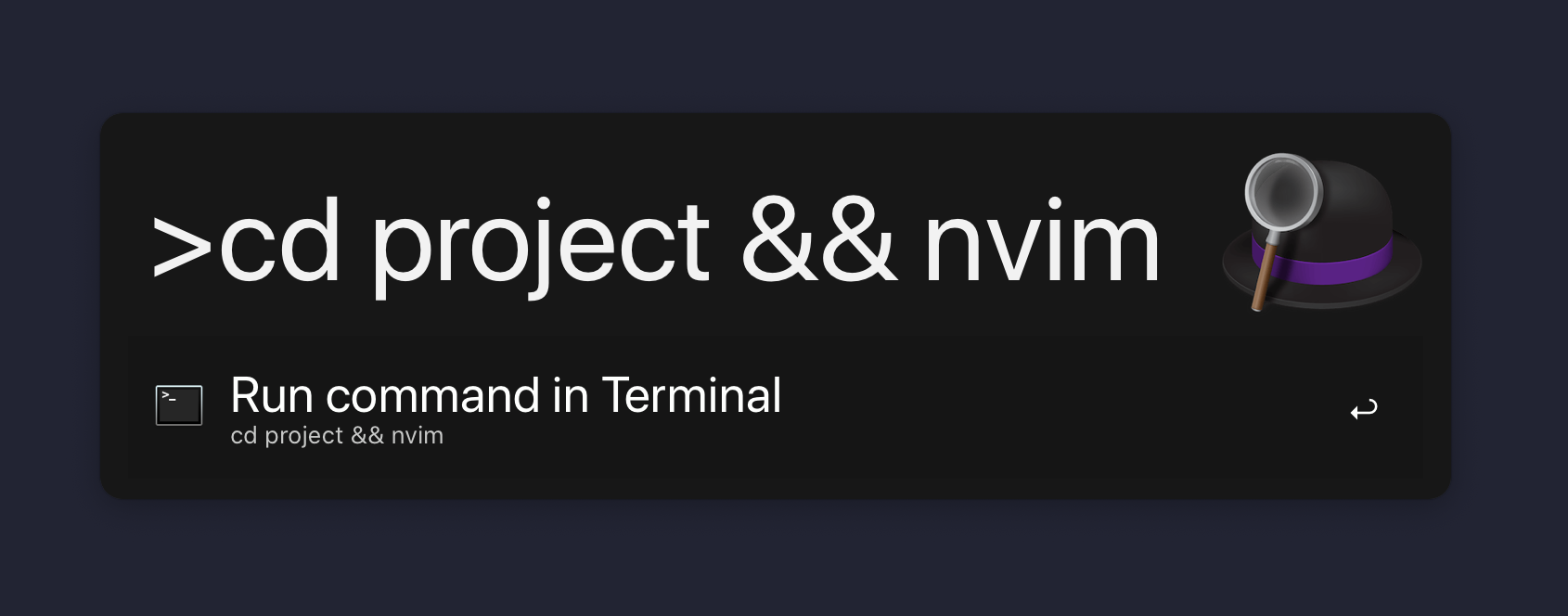
If you use my fork, just run make -j8 qinesis:default to build the
firmware.
This will generate a file called qinesis_default.hex, which you can
open with QMK Toolbox to flash your
keyboard.
To be able to flash the firmware onto your keyboard, the controller
needs to be in DFU mode, the first time you run it it should already
be in this state.
Next time you want to flash it, you need to reset the controller, they
usually have a little button on them that does just that.
Bonus stage: Sound dampening
The Advantage is a big keyboard, with lots of empty space in it. The
resonating sound this induces is not the most pleasant.
To counteract this I’ve cover the insides of the case with “roofing
felt” (carton bitumé in French) and sound proofing foam to absorb the
sound inside the keyboard; and it works quite well!
Stock:
Sound mod:
Sound mod + Switch Change:
Closing words
I was quite sad to trash a perfectly working (and expensive) keyboard, but I couldn’t be
happier with the result, the Kailh Box White are a pure clicky pleasure
and having the linear Gateron Silenced (meaning that the bottoming out
of the key is padded with rubber) Yellow on the thumbs is a bliss too.
I’m in love with that sound & touch.
Being able to use all the powers of QMK on a Kinesis keyboard is also
awesome, the possibilities are really endless; I might write about
what can be achieved with QMK in the future.
And I’m not afraid of handwiring anymore! Owning a 3D printer, I’ve
always wanted to design and wire my own keyboard, ala Dactyl
Manuform;
I hope to find the time to get this project started in the years to
come.
Feel free to reach me at my contact AT 25-47.net if you have
questions!
Links Summary