Quick post to dump some information on connecting Sparkfun’s WM8960 Audio Codec breakout board to an ESP8266.
But why?
My end goal is to connect this codec to an STM32F4 MCU, but I can’t seem to get
it to work yet.
So in order to better understand how this codec chip works and where my mistake
is, I decided to walk before I run and tried the
examples
provided by Sparkfun.
The examples and guide all run on their own “IoT RedBoard ESP32” development board, which I don’t have; however, I do have some cheap ESP8266 boards (NodeMCU V3) 1 which I will use here (this will most probably work with other ESP chips).
The wiring is different and the code also needed some changes, the examples use
the #include <drivers/i2s.h> for I2S but I wasn’t able to find it (surely it
must exists somewhere).
I was able to find esp8266/Arduino, which
provides an I2S driver.
Wiring
The WM8960 is configured via I2C, and the audio data is sent to the MCU via I2S (Inter-Integrated Circuit Sound).
I2C requires 2 wires:
- SDA (data)
- SCL (clock)
I2S requires 3 wires minimum:
- BCLK (bit clock)
- WS (word select, left/right select)
- SD (data)
The ESP8266 seems to have two IS2 ports, each seem to operate in half duplex.
One port is dedicated to receiving and the other for transmitting.
I’ve extracted the pins from reading the source code of the driver.
They are (for this example we’re only receiving data so I’m using port I2SI,
I2SO is for transmitting):
- I2S_SD: 12
- I2S_BCK: 13
- I2S_WS: 14
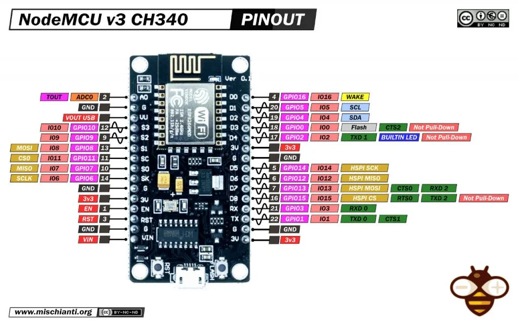
Note that these numbers refer to GPIOXX, where XX is that number.
Example I2S_SD is on GPIO12, which is marked D5 on the PCB.
For reference here is the pinout of the NodeMCU which I’m using:
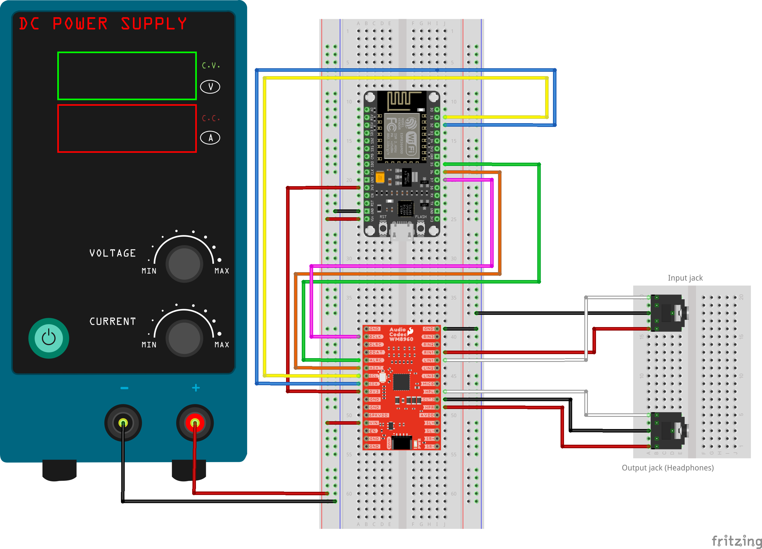
And finally here is the wiring diagram.
The input voltage from the power supply is 5V, you need this for the codec
to work, the 3.3V supplied by the ESP8266 is not enough.
Code
This code is adapted from Sparkfun’s WM8960 arduino library example 11 “Volume Plotter” To run this you will need the Arduino IDE, with the Board Definition for the 8266, which can be found here (this will also contain the I2S driver code).
I’ve modified the original code to work with the 8266, the rest is the same.
#include <I2S.h>
#include <Wire.h>
#include <SparkFun_WM8960_Arduino_Library.h>

// Click here to get the library: http://librarymanager/All#SparkFun_WM8960
WM8960 codec;
I2SClass* i2sinst;
// Define input buffer length
#define bufferLen 64
int16_t sBuffer[bufferLen];

void setup()
{
  Serial.begin(115200);

  Wire.begin();

  if (codec.begin() == false) //Begin communication over I2C
  {
    Serial.println("The device did not respond. Please check wiring.");
    while (1); // Freeze
  }

   codec_setup();
   i2sinst  = new I2SClass(false, true, true);
   int ret = i2sinst->begin(I2S_PHILIPS_MODE, 44100, 24);
}

void loop()
{

  // False print statements to "lock range" on serial plotter display
  // Change rangelimit value to adjust "sensitivity"
  int rangelimit = 3000;

  // Get I2S data and place in data buffer
  size_t bytesIn = 0;
  int rrr = i2sinst->available();
  bytesIn = i2sinst->read(&sBuffer, bufferLen);
  if (bytesIn > 0)
  {
    int16_t samples_read = bytesIn / 8;
    if (samples_read > 0) {
      float mean = 0;
      for (int16_t i = 0; i < samples_read; ++i) {
        mean += (sBuffer[i]);
      }

      // Average the data reading
      mean /= samples_read;

      // Print to serial plotter
      Serial.println(mean);
    }
  }
}

void codec_setup()
{
  // General setup needed
  codec.enableVREF();
  codec.enableVMID();

  // Setup signal flow to the ADC

  codec.enableLMIC();
  codec.enableRMIC();

  // Connect from INPUT1 to "n" (aka inverting) inputs of PGAs.
  codec.connectLMN1();
  codec.connectRMN1();

  // Disable mutes on PGA inputs (aka INTPUT1)
  codec.disableLINMUTE();
  codec.disableRINMUTE();

  // Set pga volumes
  codec.setLINVOLDB(0.00); // Valid options are -17.25dB to +30dB (0.75dB steps)
  codec.setRINVOLDB(0.00); // Valid options are -17.25dB to +30dB (0.75dB steps)

  // Set input boosts to get inputs 1 to the boost mixers
  codec.setLMICBOOST(WM8960_MIC_BOOST_GAIN_0DB);
  codec.setRMICBOOST(WM8960_MIC_BOOST_GAIN_0DB);

  // Connect from MIC inputs (aka pga output) to boost mixers
  codec.connectLMIC2B();
  codec.connectRMIC2B();

  // Enable boost mixers
  codec.enableAINL();
  codec.enableAINR();

  // Connect LB2LO (booster to output mixer (analog bypass)
  codec.enableLB2LO();
  codec.enableRB2RO();

  // Disconnect from DAC outputs to output mixer
  codec.disableLD2LO();
  codec.disableRD2RO();

  // Set gainstage between booster mixer and output mixer
  codec.setLB2LOVOL(WM8960_OUTPUT_MIXER_GAIN_0DB);
  codec.setRB2ROVOL(WM8960_OUTPUT_MIXER_GAIN_0DB);

  // Enable output mixers
  codec.enableLOMIX();
  codec.enableROMIX();

  // CLOCK STUFF, These settings will get you 44.1KHz sample rate, and class-d
  // freq at 705.6kHz
  codec.enablePLL(); // Needed for class-d amp clock
  codec.setPLLPRESCALE(WM8960_PLLPRESCALE_DIV_2);
  codec.setSMD(WM8960_PLL_MODE_FRACTIONAL);
  codec.setCLKSEL(WM8960_CLKSEL_PLL);
  codec.setSYSCLKDIV(WM8960_SYSCLK_DIV_BY_2);
  codec.setBCLKDIV(4);
  codec.setDCLKDIV(WM8960_DCLKDIV_16);
  codec.setPLLN(7);
  codec.setPLLK(0x86, 0xC2, 0x26); // PLLK=86C226h
  //codec.setADCDIV(0); // Default is 000 (what we need for 44.1KHz)
  //codec.setDACDIV(0); // Default is 000 (what we need for 44.1KHz)
  codec.setWL(WM8960_WL_24BIT);

  codec.enablePeripheralMode();

  // Enable ADCs, and disable DACs
  codec.enableAdcLeft();
  codec.enableAdcRight();
  codec.disableDacLeft();
  codec.disableDacRight();
  codec.disableDacMute();

  codec.disableLoopBack();

  // Default is "soft mute" on, so we must disable mute to make channels active
  codec.enableDacMute();

  codec.enableHeadphones();
  codec.enableOUT3MIX(); // Provides VMID as buffer for headphone ground

  codec.setHeadphoneVolumeDB(0.00);
}
Now plug in some form of audio source in the input jack (connected to R/LIN3 on the codec), and if everything went well you should see something like this:
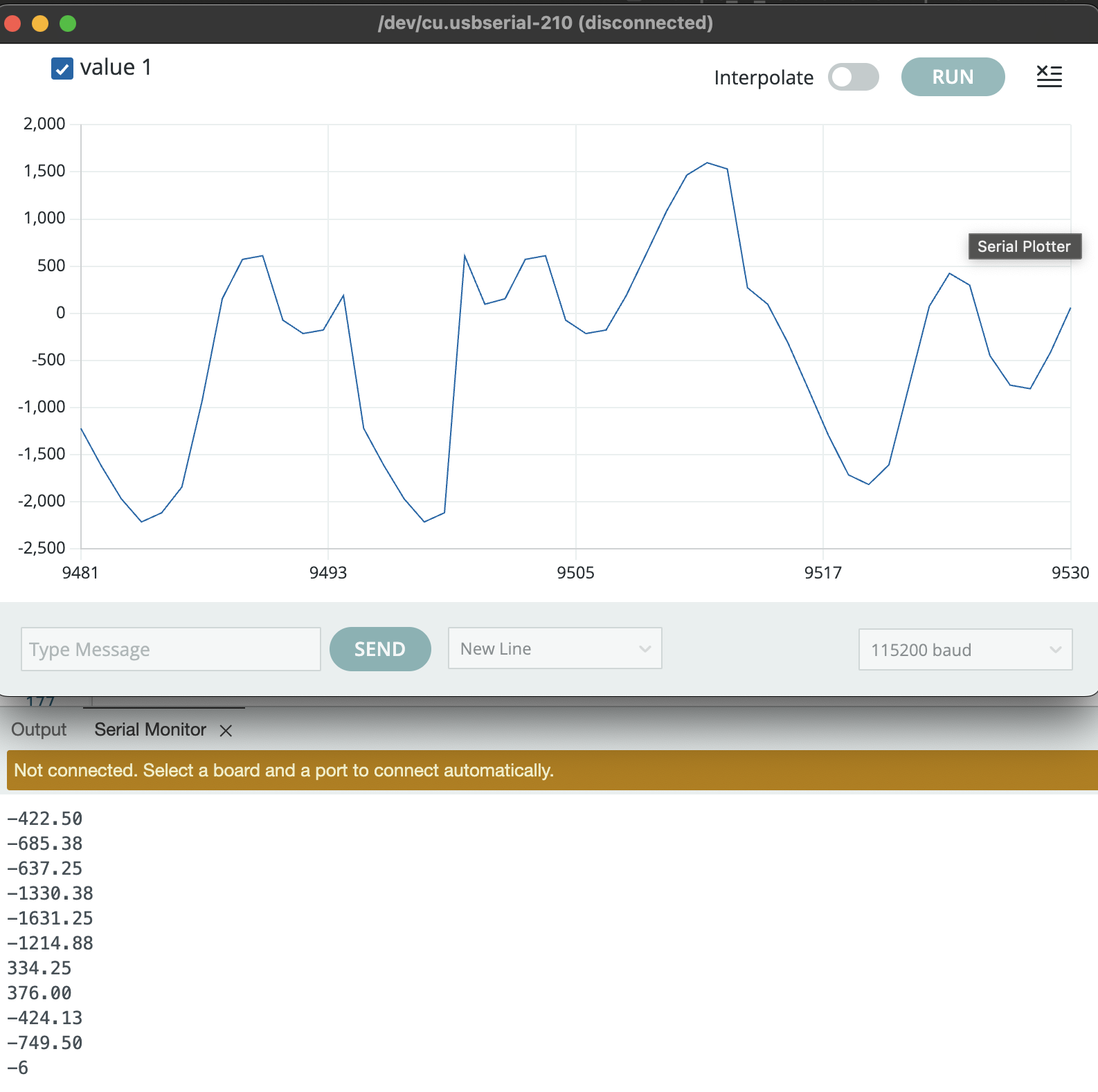
Cheers!
Don’t buy ESP8266, ESP has expanded their offering since and any ESP32 will be better suited and cost as much. I purchased those long ago.↩︎